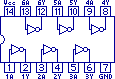
 Basically on each chip you can stick in a high voltage and get a low voltage out and visa versa. One pin goes in, one comes out and there are 6 pairs (hence the Hex). Now the Z80 has 13 control pins and so I opted to get 2 Hex Inverters. Ok so that lets me control 12 pins on the Z80, so I will just hook up any pins I don't really need to use at this stage to the +5V supply (remember high voltage means OFF).
 At this point I would like to thank Hackman's Realm for a description of how to get a Z80 working. After several attempts at wiring the Z80 to the Arduino I am surprised I didn't blow one of them up by connecting thing up the wrong way, and Hackman's document put me on the right path (I did say I didnt know what I was doing at the start :) ).
So now I can tell the Arduino to set a pin HIGH i.e. ON and via the 74LS04 chip the Z80 gets a LOW signal turning the pin ON.
So what I send to the CPU is NOT what I sent but satisfies the 'active Low' requirements and everyone is happy!
No comments:
Post a Comment